Corridor Cleanup
Designed for the savvy Civil 3D corridor user, this tool addresses corridor management. Users can select multiple corridors, baselines and regions, and in one click, remove all surface, width, and/or slope targets. This tool will help users quickly reconstruct their corridor regions without the need for tedious target removal or completing deleting the corridor or region.
- Automatically remove corridor targets from one or more corridors, baselines or regions
- Greatly improves corridor updating and management time
Feature Line to Alignment
Created for all Civil 3D users, this tool provides a much-needed data-conversion method in Civil 3D. It generates an alignment and layout profile from a feature line. Used by surveyors to stakeout site feature lines such as curb, or designers needing data conversions without the need for redrawing, this tool is highly valuable in all Civil 3D workflows.
- Convert feature lines and survey figures to alignments and profiles
- Improve workflows for construction staking and general data conversion
Parts Swapper
Built for all Civil 3D pipe network users, this tool allows the swapping of multiple parts, both structures and pipes, for alternatives. Users can select parts in plan, profile view, or by pipe network name. Parts will be swapped similar to the native Swap Parts command, but allows it to be performed on multiple parts at a time.
- Swap multiple parts, both pipes and structures, in a single command
- Select in plan or profile view, or by pipe network
- Update entire sections of your pipe networks at once
Survey Sweeper
Built for the survey Civil 3D user, this tool takes the tedium out of working with survey databases. It will simultaneously delete selected survey points and survey figures from drawings and survey databases. Users will find this a big time saver when deleting unwanted data generated through linework processing, or other common missteps in working with survey databases.
- Simultaneously delete selected survey points and figures in drawings AND survey databases
- Automate typically tedious processes to keep your databases and drawings in sync
Data Wizard
Data Wizard creates project-specific legends and quantity takeoffs of both AutoCAD and Civil 3D objects. It will scan one or more drawings for all point, line and/or area-type objects, and create a dynamic AutoCAD table, including text and symbology that’s typically shown.
Objects can include blocks, cogo & survey, points, multileaders, hatches, lines, 2D & 3D polylines, survey figures, feature lines, parcel segments, and alignments. Legend and quantify takeoff settings can be saved in different templates for quick and easy execution by end users.
- Creates project-specific legends or quantity takeoffs of AutoCAD and Civil 3D objects
- Specify one or more drawings, or limit to a sheet, and scan for chosen object types
- Objects include all AutoCAD and Civil 3D point, line and area-type objects
- Save template files for easy creation of legends or takeoffs in the future
Label Genie
Automatically label your sheets and drawings with both Civil 3D and AutoCAD annotation. Choose anchor objects through property filters, then insert hundreds of labels at once on surfaces, lines and curves, alignments, mtext, leaders, blocks, and more.
This tool works on multiple drawings and layouts at the same time. Users have detailed control of label insertion, including offsets, rotation, scaling, styles, and more. AutoCAD label text can be populated with custom text, or AutoCAD fields can be inserted to generate dynamic links to anchor objects. Save labeling “scenarios” for quick repeat on other projects or drawings. Label Genie will accomplish what typically takes hours or days of work in a fraction of the time.
- Automatic labeling and annotation
- Eliminate hours of tedious click-by-click annotation
- Civil 3D and AutoCAD annotation inserted across multiple drawings, layouts, viewports
- Save labeling “scenarios” for quick repeat
Sheet Generator
Sheet Generator will create plan and/or profile sheets, similar to the native Viewframes toolset, but allows dynamic updating of sheets. Users will be able to create “viewshapes” in model space, then edit them and “push” changes to sheets. Viewport size and position, profile views, north arrow, sheet numbering, Matchline text and more, are all dynamically linked to model space “viewshapes.”
- Create dynamically-linked plan and/or profile sheets
- Update sheets by editing “viewshapes” in model space
- Automatic updating of viewports, profile views, sheet set fields, matchlines, and more
- Automatic profile matchline placement & setting of profile station/elevation
Auto Grader
Create site grading models that are dynamic and stable at the same time. Define “parent” feature lines through native methods, then create grading families to both generate and update “child” feature lines. “Parent” lines can be anything, but might include gutter lines, pond tops, or right-of-way lines in subdivisions. Plug in distance, slope, and daylight parameters to create back/top of curb, pond benches, or side and back of lot feature lines.
When “parent” lines change, refresh grading families to automatically update “child” lines. Breaklines are automatically added to surfaces. Layer and style assignment is automated through user settings. Truly effective site grading in Civil 3D has arrived with Auto Grader!
- Create dynamic grading models by linking feature line sets
- Define “parent” feature lines, then auto-generate “child” feature lines
- Refresh grading models as “parent” feature lines change
- Breaklines are automatically added to surfaces
Corridor Mapper
The Corridor Mapper will allow for corridor targets to be automatically assigned by mapping layers to subassemblies. Users can define a “mapping” for a given for a given corridor, then simply create target objects on those layers and the corridor will automatically assign those targets to the appropriate subassemblies.
This tool completely replaces the native Target Mapping dialog box with a much more dynamic and powerful option.
- Automatically assign corridor targets by mapping layers to subassemblies
- Maintain a dynamic link between mapped layers to subassemblies
- Continue to draw target objects and automatically assign targets with previously mapped layers
- Automatically rename layers to match subassemblies, or vice versa
Corridor Merger
The Corridor Merger will combine multiple corridors into one. All corridor baseline and region definitions will merge into one corridor, including assemblies, station limits, frequency, targets, and overrides. Users have options to create surfaces based on previously defined surface definitions.
- Merge two or more corridors into one
- Maintain all targets and settings from merged corridors
- Create merged surfaces from merged corridors
Corridor Splitter
This tool allows a single corridor to be split into two corridors. All original corridor properties, including targets, frequencies, surfaces, and more, will remain intact, saving a lot of time. The user can select which regions and baselines will belong to which corridor.
Users have additional options to rename the new corridors, as well as the baseline and region names.
- Split one corridor into two, maintaining all settings and surfaces
- Speed up corridor management time
Earthwork Processor
Generate detailed earthwork definitions by creating earthwork sets, and provide an existing and proposed surfaces, as well as polylines or feature lines to represent varying subgrade depths across the site, and Earthwork Processor will do the rest, including generating a dynamic subgrade surface, accounting for topsoil stripping, and resulting in cuts and fills per region.
When designs change, simply refresh the earthwork set and everything will be updated automatically. Results can be labeled, shaded, inserted in AutoCAD tables, and exported to a spreadsheet file.
- Calculate complex site earthworks utilizing dynamic Civil 3D surfaces
- Account for different depths across the site, as well as topsoil stripping
- Automatically label, shade, table or export results
- Save out earthwork sets for easy repetition in other projects
Pipe Designer
Built for all Civil 3D pipe network users, this tool facilitates network design inside Civil 3D drawings with a spreadsheet editor. Users can design entire pipe runs by editing slopes and invert drops, interpolating slopes between parts and applying rules. Users can design upstream, downstream, or both.
- Design entire pipe network runs with a spreadsheet editor inside Civil 3D
- Design by slope or invert, match pipes by crown or invert, and lock key values
- Apply rules, interpolate slopes between parts, and set parts to minimum cover
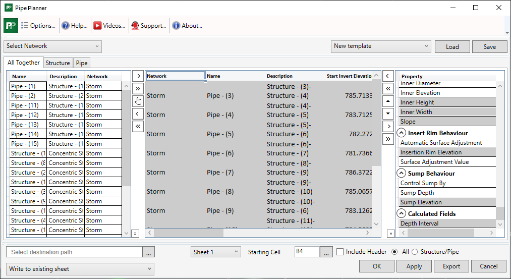
Pipe Planner
Load pipe networks in an in-app spreadsheet or export to a spreadsheet file. Edit parameters and perform analyses in the spreadsheet, then push changes back to the pipe network. Create customized manhole schedules, pipe depth reports, and detailed QTO, all through one intuitive interface.
- Import/export pipe networks to and from a spreadsheet file
- Edit parameters in spreadsheet software or the in-app spreadsheet editor, then push changes to the pipe networks
- Create custom manhole schedules, pipe depth reports, and detailed QTO
Parts Tagger
Tabling and labeling of important pipe network structure or pipe part data, such as grate or casting, can be a tedious process. Users must manually enter these values in each part’s properties dialog box. This tool provides an interface to push user-defined values for grate, cover, frame, and material to multiple structures in a single command. This makes creation of manhole schedules much faster. Pipes can now have their reference surface, reference alignment, and description modified with the latest update.
- Populate grate, casting, and other values to multiple pipes and structures at once
- Helps automate detailed pipe/manhole schedules and pipe/structure labeling
- Quickly assign or reassign the reference surface and reference alignment for both pipes and structures
Layer Trace
Layer and styles management in Civil 3D can be a tedious process. This tool will allow the tracking of layers referenced in Civil 3D styles. This is a great benefit for performing template (.dwt) maintenance and updating, as well as for keeping project drawings clean and organized. Upon choosing a given layer, the tool will show all styles that use that layer.
The user can then choose to swap out that layer for another (with one or more styles), or to edit a style’s layers right within the tool. The user can then purge styles if there are no other references, and/or delete layers if there are no other references.
- Save time by tracking layer use in Civil 3D styles
- Automatically swap or purge layers from styles
Point File Converter
Convert survey point files from one code list to another, allowing field work in one code list, and CAD processing in another. Through a simple spreadsheet “translation file” that spells out the code conversions, the tool will read the conversions and apply them to one or more point files. Line work codes, as well as prefixes and suffixes in coding, are all accounted for.
- Convert survey point files from one code list to another in less than a second
- Create easy spreadsheet “translation files” to spell out the conversion between coding standards
- Accounts for line work codes, as well prefixes and suffixes, in the point file
- Works with common point file types (.csv, .txt, etc.)


 Corridor Cleanup
 Feature Line to Alignment
 Parts Swapper
 Survey Sweeper
 Data Wizard
 Label Genie
 Sheet Generator
 Auto Grader
 Corridor Mapper
 Corridor Merger
 Corridor Splitter
 Earthwork Processor
 Pipe Designer
 Pipe Planner
 Parts Tagger
 Layer Trace
 Point File Converter